₹11,999.00 ₹9,999.00
Important Notes
Project Code : PF_XBEE_6
1.This project we have done on Arduino uno microcontroller
2.Same project possible on ESP32 and raspberry pi pico controller
3.Laptop not included in project
4.Along with project we will provide
a. original code
b. circuit diagram
c. Documentation data
5.This project IEEE reference titles
a. Energy Monitoring System Using Zigbee and Arduino
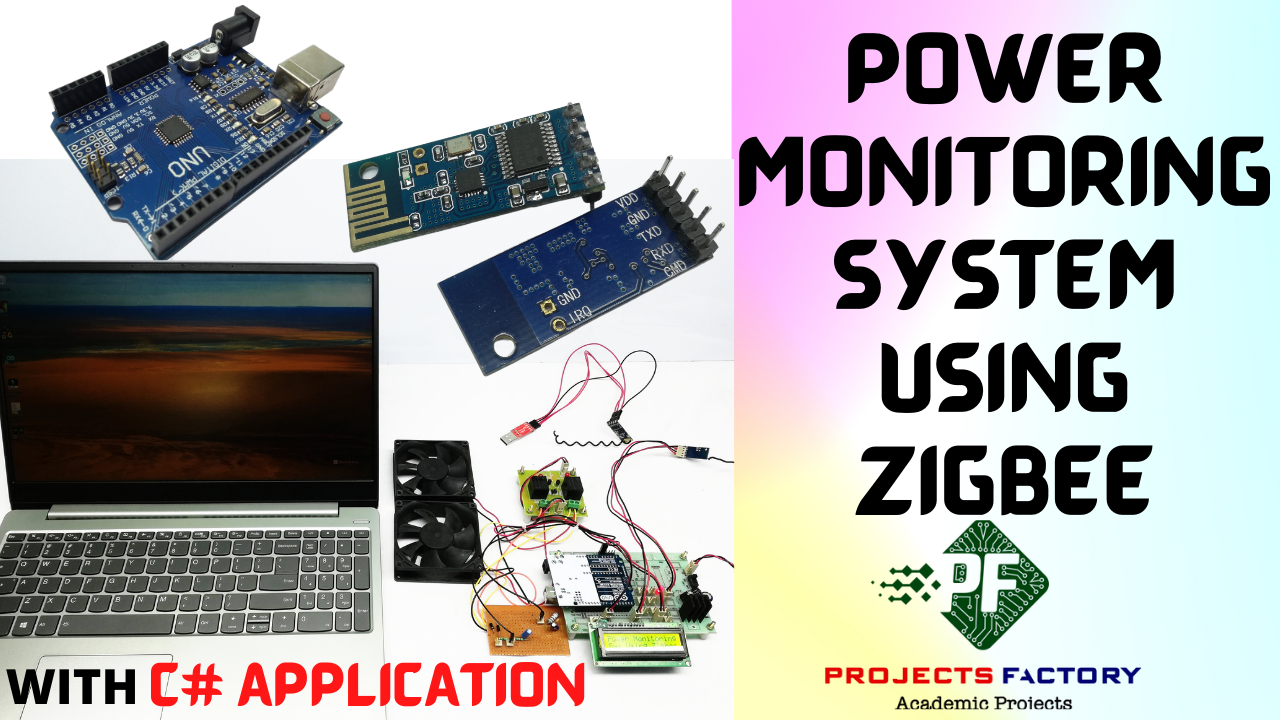
Power Monitoring System Using Zigbee
AIM:
Design and Development of Power monitoring system using Zigbee.
PURPOSE:
In recent times every one installed DC appliances like DC fan, DC bulbs and DC based other appliances. But DC appliances consume less power. Reading DC power is useful for these kinds of devices. Here we are going to design power monitoring system using ZIGBEE. Using this we can monitor power from remote location.
DESCRIPTION:
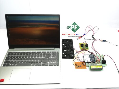
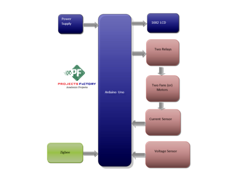
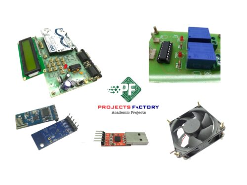
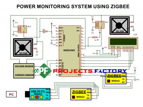
This project includes Zigbee module (HC12), which is connected to Arduino through UART interface. Two DC fan/motor controlled by two relays which are connected to Arduino digital pins. Voltage and Current sensors connected to Arduino Analog pins.
WORKING:
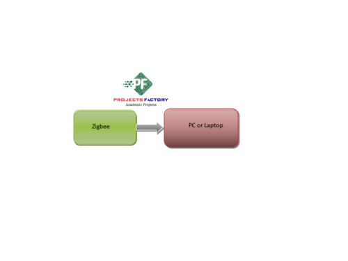
Here there are two sections. One is transmitter and other is receiver. Transmitter side Arduino, Zigbee, Two Relays, Two fans/motors, voltage and current sensors interfaced. Arduino calculates voltage and current of two loads. User can control two loads from receiver section. Receiver section consists of Zigbee and pc or laptop. Based on number of loads current consumption will increase. Based on current and voltage, power will be calculated. These values will display on 16X2 LCD. Also these values displaying on serial monitor at receiver side.
TECHNICAL SPECIFICATIONS:
HARDWARE:
Microcontroller : Arduino Uno
Crystal : 16 MHz
LCD : 16X2 LCD
Zigbee Module : HC12 – 433MHZ or 2.4Ghz
Voltage Sensor : Resistor voltage divider
Current Sensor : Resistor voltage divider and 1 ohm shunt resistance
Relay : 12v DC
Fan/Motor : 5V/12V DC
Power Source : 12v 2 amp Adaptor
SOFTWARE:
Arduino IDE
Proteus based circuit diagram
APPLICATIONS:
- Power Monitoring applications
- Power Meters applications
- Power saving applications
INTERFACES COVERD:
- We have covered Zigbee (433Mhz or 2.4Ghz – HC12) module interfacing
- Voltage sensor and current sensor interfacing




Reviews
There are no reviews yet.