DOWNLOAD ABSTRACT
AIM:
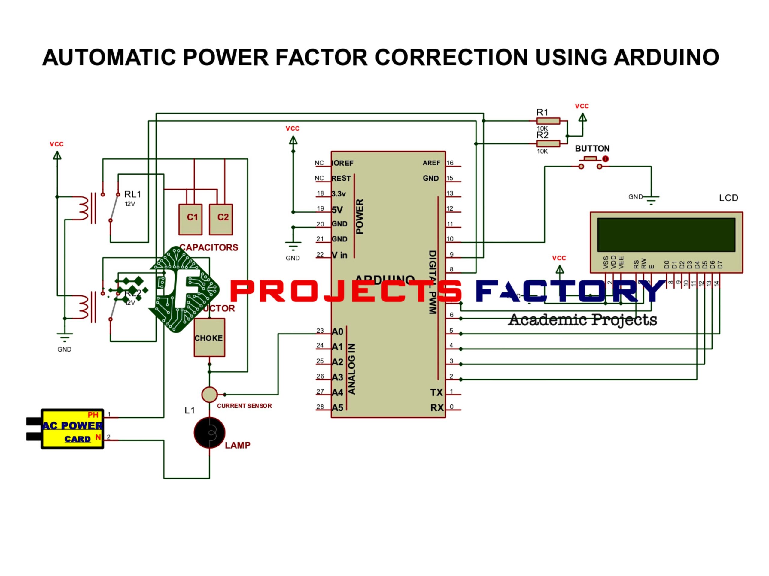
Design and Development of power factor correction Using Arduino.
PURPOSE:
Power factor correction is very hot topic in electrical industry. Every one applies power factor correction to overall industry to increase efficiency of power usage. Let’s discuss about power factor correction and its uses. Generally any load consumes power and some power will waste in the form of heat or other form. By reducing losses we can improve power consumption efficiency. Generally power loses in inductor based loads. By adding capacitor bans to load in parallel we can increase power consumption efficiency. Here we will use Arduino to implement power factor correction. If power factor value near to one, that means high power efficiency. Power factor value nothing but output power by (division) input power.
DESCRIPTION:
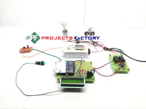
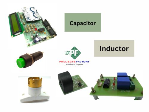
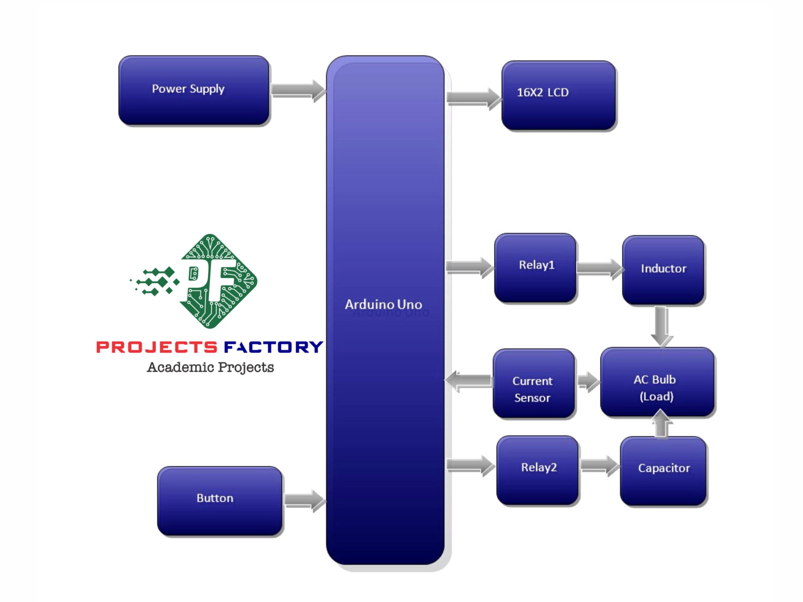
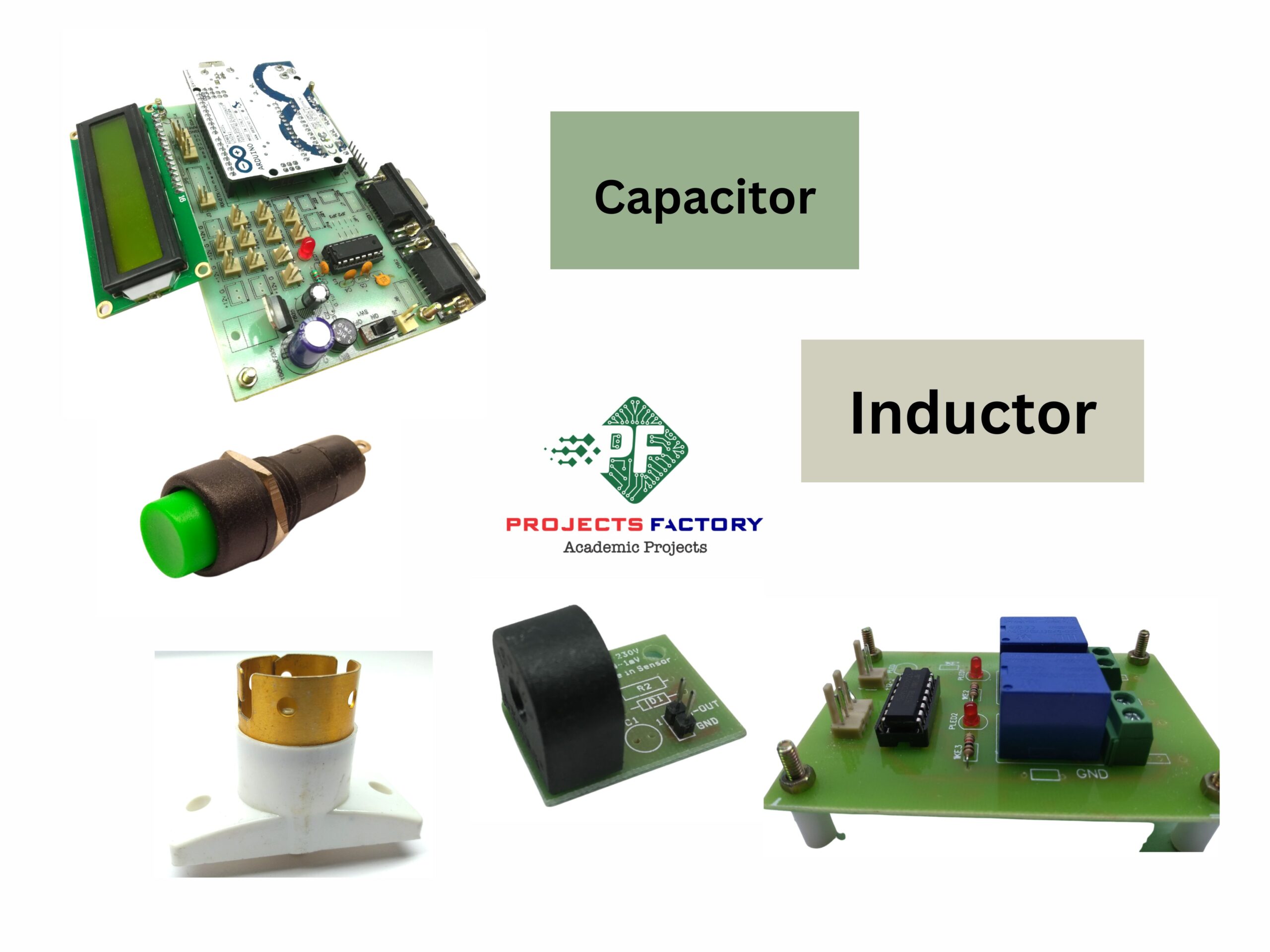
Coil type current sensor connected to Arduino analog pin. Two relays connected to Arduino digital pins. 16×2 LCD display connected to Arduino digital pins.
WORKING:
Here we used 230v AC bulb as load. By default it has near unity power factor because of resistive nature. To show lagging we will add inductor through relay. When inductor added through series to light, light will be dim and consumes less power. This is nothing but lagging. Arduino reads current value and identify lagging condition. Then Arduino ON capacitor bank parallel to light and light brightness will be increased, that means power factor is in leading. Also on LCD it shows power factor values when load was in lagging and leading condition.


Reviews
There are no reviews yet.