DOWNLOAD ABSRACT
AIM:
Design and Development of Power Factor Correction and Alert using GSM Module.
PURPOSE:
The ratio of output power to input power decides power factor value of any load. It should be unity or near to unity. Otherwise system is in lagging mode. If unity then lagging mode. Any industry or electrical system is in leading then we can consider it has good power factor value. To find out power factor value, current is key parameter. System needs to read input current and load consumption current. Based on current, power will be calculated. This system will send SMS when leading, lagging and normal mode. The proposed project title is power factor correction and alert using GSM module with Arduino.
DESCRIPTION:
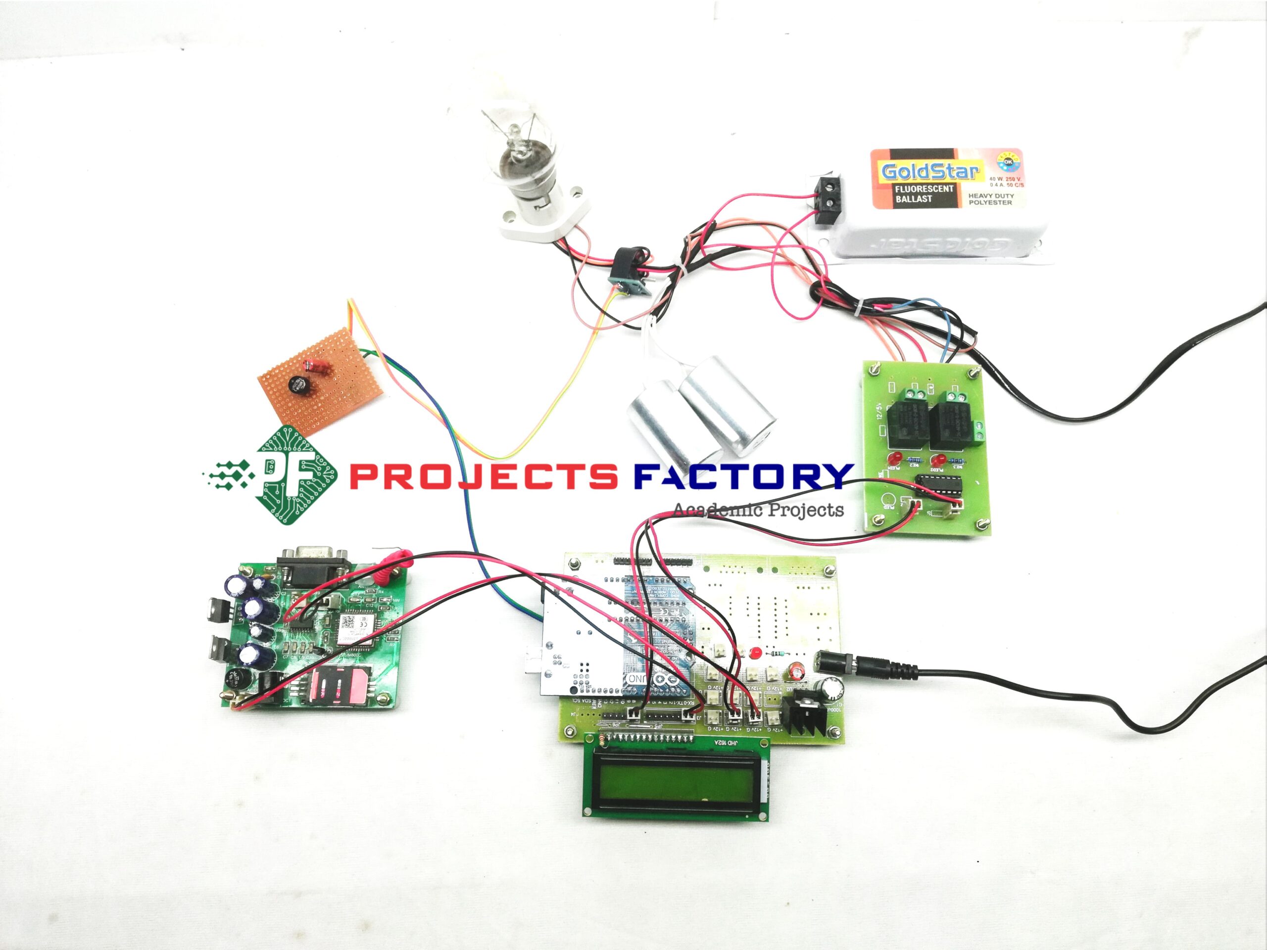
GSM module (SIM800C) interfaced with Arduino UART port. Coil type current sensor connected to Arduino analog pin. Two relays connected to Arduino digital pins. 16×2 LCD display connected to Arduino digital pins.
WORKING:
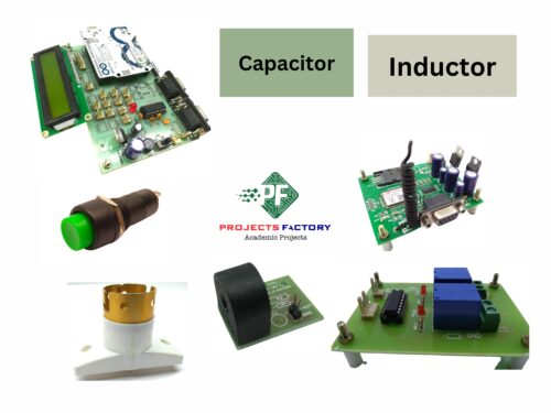
For AC bulb power factor value is unity because of resistive type and it will be load. In this project we will show normal mode, lagging mode and leading mode and send SMS. When button pressed first time then load will be ON. Here load is AC bulb and it is resistive type. Input power and output power almost same, so that power factor almost unity. When switch pressed second time then inductor will be ON in series to load. Then lot of power consumed in inductor and less power went into bulb. This means load is in lagging mode and power factor value far away from unity. When we pressed button third time then capacitor will ON in parallel to load and power will increase at load side. This condition nothing but leading and power factor value near to unity. In each and every condition SMS will send to mobile number.
TECHNICAL SPECIFICATIONS:
HARDWARE:
Microcontrollers : Arduino Uno
Crystal : 16 MHz
LCD : 16X2 LCD
Load : 230V AC Resistive Type
GSM Module : SIM800C
Inductor : 40W 230V AC
Capacitor Banks : 2.50 MFD
Relays : 12V DC Electrolytic
Power Source : 12VDC Battery
SOFTWARE:
Arduino IDE
Proteus based circuit diagram
APPLICATIONS:
- Automatic power factor correction
- Automatic power factor controller (APFC)
- Current measurement and power factor with GSM
INTERFACES COVERD:
- We have covered power reading mechanism of load and GSM module (SIN800C) interface
- Interfacing inductor and capacitor banks


Reviews
There are no reviews yet.