DOWNLOAD ABSTRACT
AIM:
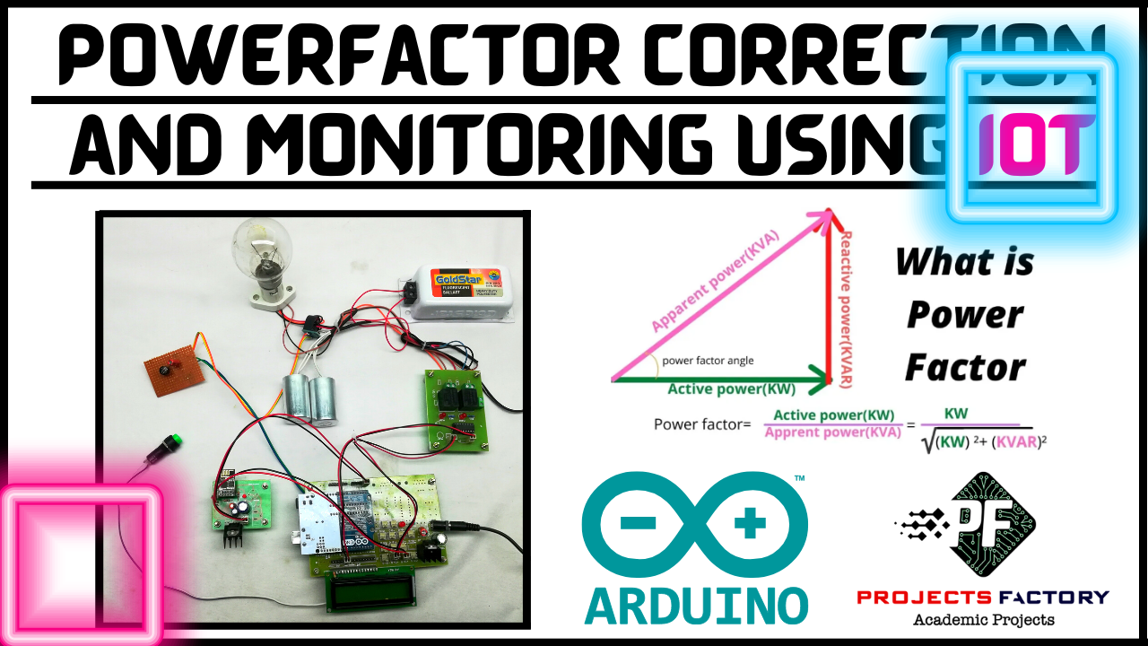
Design and Development of Automatic Power Factor Correction and Monitoring using IOT.
PURPOSE:
Power factor is very important in industrial applications. Most of the domestic application loads are resistive type. For resistive type of loads, power factor value is equal or near to unity. But, in industries most of the loads are inductive type. Example- Motors, pumps, Conveyor belts and many more. All are inductive type and energy losses are high. If high energy losses, then power factor value away from unity. To maintain power factor near to unity, need to add capacitor banks to loads. Proposed project title is automatic power factor correction and monitoring using IOT with Arduino microcontroller.
DESCRIPTION:
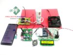
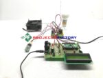
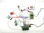
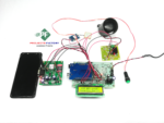
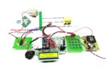
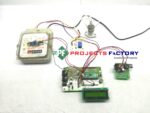
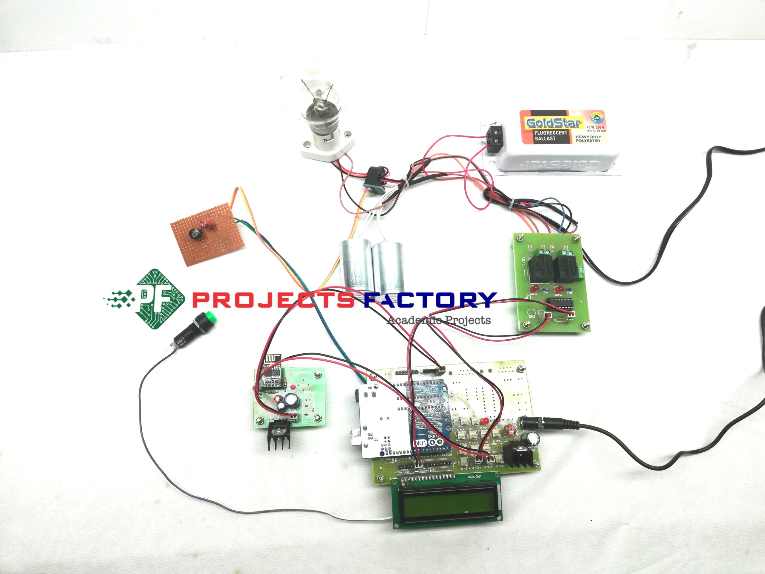
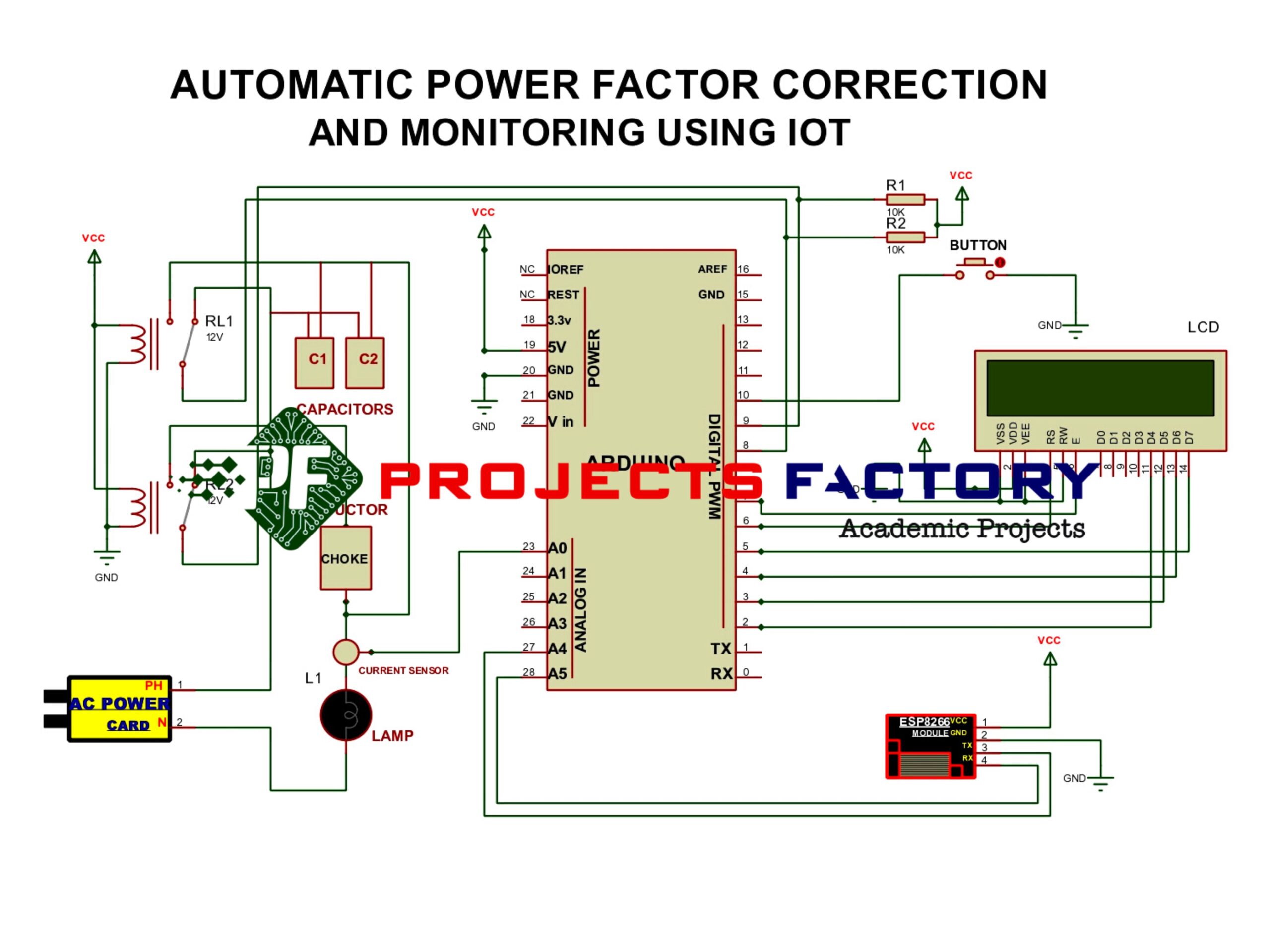
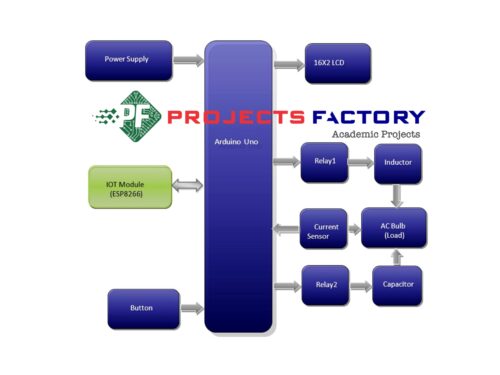
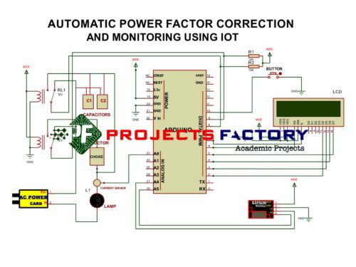
ESP8266 module interfaced with Arduino UART port. Coil type current sensor connected to Arduino analog pin. Two relays connected to Arduino digital pins. 16×2 LCD display connected to Arduino digital pins.
WORKING:
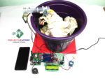
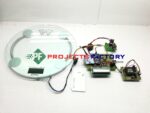
ESP8266 is nothing but IOT module. It can send data to IOT cloud server. Power factor value and power factor condition will update to IOT server. 230V AC bulb is main output power load. By default power factor value is unity because of resistive nature of bulb. The ratio of output power to input power almost equal for resistive loads. To show lagging condition, we will press button then condition will be in lagging that means inductor will ON series to load. Then power factor value away from unity. If we press button again then condition will be leading, that means capacitor banks will be ON parallel to load then power factor value equal to unity. For each condition Arduino reads current and calculate power and estimate leading and lagging conditions. In each condition Arduino sends power factor value to IOT cloud server.


Reviews
There are no reviews yet.